
HPE FlexFabricスイッチでRRPPを設定してみた
こんにちは。ネットワークソリューション特集 編集部です。
今回は、HPE FlexFabricスイッチのRRPP設定についてご紹介します。
RRPP(Rapid Ring Protection Protocol)とは
RRPPは、ネットワーク内のスイッチ間でリング状のイーサネットトポロジーを作成し、ノード間の通信を冗長化するプロトコルです。
これにより、ネットワーク内の1つのスイッチ、またはリンクの障害が発生しても、トラフィックを維持することができます。
RRPP は、リングが正常な場合に、ループによって発生するブロードキャストストームを防ぐことができます。
またリング上のリンクが切断されたときに、ノード間の通信経路を迅速に復旧することができます。
今回は最小構成のシングルリングの設定をしていきます。
RRPP構成
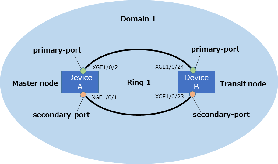
RRPPの構成は下記としました。
・HPE Networking Comwareスイッチシリーズ 5710 を2台で構成
・デバイス A、デバイス Bは、RRPPドメイン1を形成します。
・RRPPドメイン1のプライマリ制御VLANをVLAN1000として指定します。
・RRPPドメイン1のデータVLANをVLAN 999として指定します。
・デバイス A、デバイス Bは、プライマリリング1を形成します。
・デバイス Aをプライマリリング1のマスターノードとして指定します。
・デバイス AのTen-GigabitEthernet1/0/2をプライマリポートとして、Ten-GigabitEthernet1/0/1をセカンダリポートとします。
・デバイス Bをプライマリリング1のトランジットノードとします。
・デバイス BのTen-GigabitEthernet 1/0/24をプライマリポートとして、Ten-GigabitEthernet2/0/23をセカンダリ ポートとします。
RRPPの設定
1.デバイスA(マスターノード)
<DeviceA> system-view
【データ用VLANの作成】
[DeviceA] vlan 999
【RRPPではデータ用VLANはMultiple Spanning Tree Instances (MSTI) を参照するのでその設定をします】
[DeviceA] stp region-configuration
[DeviceA-mst-region] region-name RG1
[DeviceA-mst-region] instance 1 vlan 999
[DeviceA-mst-region] active region-configuration
[DeviceA-mst-region] quit
【インターフェースにデータ用VLANを設定します。モードはtrunkで、STPもOFFにします】
[DeviceA] interface ten-gigabitethernet 1/0/2
[DeviceA-Ten-GigabitEthernet1/0/2] undo stp enable
[DeviceA-Ten-GigabitEthernet1/0/2] port link-type trunk
[DeviceA-Ten-GigabitEthernet1/0/2] undo port trunk permit vlan 1
[DeviceA-Ten-GigabitEthernet1/0/2] port trunk permit vlan 999
[DeviceA-Ten-GigabitEthernet1/0/2] quit
[DeviceA] interface ten-gigabitethernet 1/0/1
[DeviceA-Ten-GigabitEthernet1/0/1] undo stp enable
[DeviceA-Ten-GigabitEthernet1/0/1] port link-type trunk
[DeviceA-Ten-GigabitEthernet1/0/1] undo port trunk permit vlan 1
[DeviceA-Ten-GigabitEthernet1/0/1] port trunk permit vlan 999
[DeviceA-Ten-GigabitEthernet1/0/1] quit
【RRPPドメインを作成します。制御VLANは1000(データ用VLANと別のVLAN IDを使用する。)インスタンスは先に作成したMSTIの1とします。】
[DeviceA] rrpp domain 1
[DeviceA-rrpp-domain1] control-vlan 1000
[DeviceA-rrpp-domain1] protected-vlan reference-instance 1
【モードをマスターにして、プライマリ、セカンダリポートを指定します。Levelは0(プライマリリング)を指定します】
[DeviceA-rrpp-domain1] ring 1 node-mode master primary-port ten-gigabitethernet 1/0/2 secondary-port ten-gigabitethernet 1/0/1 level 0
[DeviceA-rrpp-domain1] ring 1 enable
[DeviceA-rrpp-domain1] quit
【最後にRRPPを有効にします】
[DeviceA] rrpp enable
2.デバイスB(トランジットノード)
<DeviceB> system-view
【データ用VLANの作成】
[DeviceB] vlan 999
【RRPPではデータ用VLANはMultiple Spanning Tree Instances (MSTI) を参照するのでその設定をします】
[DeviceB] stp region-configuration
[DeviceB-mst-region] region-name RG1
[DeviceB-mst-region] instance 1 vlan 999
[DeviceB-mst-region] active region-configuration
[DeviceB-mst-region] quit
【インターフェースにデータ用VLANを設定します。モードはtrunkで、STPもOFFにします】
[DeviceB] interface ten-gigabitethernet 1/0/24
[DeviceB-Ten-GigabitEthernet1/0/24] undo stp enable
[DeviceB-Ten-GigabitEthernet1/0/24] port link-type trunk
[DeviceB-Ten-GigabitEthernet1/0/24] undo port trunk permit vlan 1
[DeviceB-Ten-GigabitEthernet1/0/24] port trunk permit vlan 999
[DeviceB-Ten-GigabitEthernet1/0/24] quit
[DeviceB] interface ten-gigabitethernet 1/0/23
[DeviceB-Ten-GigabitEthernet1/0/23] undo stp enable
[DeviceB-Ten-GigabitEthernet1/0/23] port link-type trunk
[DeviceB-Ten-GigabitEthernet1/0/23] undo port trunk permit vlan 1
[DeviceB-Ten-GigabitEthernet1/0/23] port trunk permit vlan 999
[DeviceB-Ten-GigabitEthernet1/0/23] quit
【RRPPドメインを作成します。制御VLANは1000(IDはデータ用VLANと被らないように。)インスタンスは先に作成したMSTIの1とします】
[DeviceB] rrpp domain 1
[DeviceB-rrpp-domain1] control-vlan 1000
[DeviceB-rrpp-domain1] protected-vlan reference-instance 1
【モードをトランジットにして、プライマリ、セカンダリポートを指定します。Levelは0(プライマリリング)を指定します。】
[DeviceB-rrpp-domain1] ring 1 node-mode transit primary-port ten-gigabitethernet 1/0/24 secondary-port ten-gigabitethernet 1/0/23 level 0
[DeviceB-rrpp-domain1] ring 1 enable
[DeviceB-rrpp-domain1] quit
【最後にRRPPを有効にします。】
[DeviceB] rrpp enable
正常時ステータス確認
1.デバイスA(マスターノード)
<DeviceA>display rrpp brief
Flags for node mode: M — Master, T — Transit, E — Edge, A — Assistant-edge
RRPP protocol status: Enabled
Domain ID : 1
Control VLAN : Primary 1000, Secondary 1001
Protected VLAN: Reference instance 1
Hello timer : 1 sec, Fail timer: 3 sec
Linkup-Delay timer: 0 sec
Fast detection status: Disabled
Fast-Hello timer: 20 ms, Fast-Fail timer: 60 ms
Fast-Edge-Hello timer: 10 ms, Fast-Edge-Fail timer: 30 ms
Ring Ring Node Primary/Common Secondary/Edge Enable
ID level mode port port status
——————————————————————————
1 0 M XGE1/0/2 XGE1/0/1 Yes
<DeviceA>display rrpp verbose domain 1
Domain ID : 1
Control VLAN : Primary 1000, Secondary 1001
Protected VLAN: Reference instance 1
Hello timer : 1 sec, Fail timer: 3 sec
Linkup-Delay timer: 0 sec
Fast detection status: Disabled
Fast-Hello timer: 20 ms, Fast-Fail timer: 60 ms
Fast-Edge-Hello timer: 10 ms, Fast-Edge-Fail timer: 30 ms
Ring ID : 1
Ring level : 0
Node mode : Master
Ring state : Complete
Enable status : Yes, Active status: Yes
Primary port : XGE1/0/2 Port status: UP
Secondary port: XGE1/0/1 Port status: BLOCKED
<DeviceA>display rrpp statistics domain 1
Ring ID : 1
Ring level : 0
Node mode : Master
Active status : Yes
Primary port : XGE1/0/2
Fast-Hello packets: 0 Sent, 0 Received
Fast-Edge-Hello packets: 0 Sent, 0 Received
Direct Hello Link Common Complete Edge Major Total
down flush FDB flush FDB hello fault
——————————————————————————
Out 481 0 0 0 0 0 481
In 0 0 0 0 0 0 0
Secondary port: XGE1/0/1
Fast-Hello packets: 0 Sent, 0 Received
Fast-Edge-Hello packets: 0 Sent, 0 Received
Direct Hello Link Common Complete Edge Major Total
down flush FDB flush FDB hello fault
——————————————————————————
Out 0 0 0 0 0 0 0
In 481 0 0 0 0 0 481
2.デバイスB(トランジットノード)
<DeviceB>display rrpp brief
Flags for node mode: M — Master, T — Transit, E — Edge, A — Assistant-edge
RRPP protocol status: Enabled
Domain ID : 1
Control VLAN : Primary 1000, Secondary 1001
Protected VLAN: Reference instance 1
Hello timer : 1 sec, Fail timer: 3 sec
Linkup-Delay timer: 0 sec
Fast detection status: Disabled
Fast-Hello timer: 20 ms, Fast-Fail timer: 60 ms
Fast-Edge-Hello timer: 10 ms, Fast-Edge-Fail timer: 30 ms
Ring Ring Node Primary/Common Secondary/Edge Enable
ID level mode port port status
——————————————————————————
1 0 T XGE1/0/24 XGE1/0/23 Yes
<DeviceB>display rrpp verbose domain 1
Domain ID : 1
Control VLAN : Primary 1000, Secondary 1001
Protected VLAN: Reference instance 1
Hello timer : 1 sec, Fail timer: 3 sec
Linkup-Delay timer: 0 sec
Fast detection status: Disabled
Fast-Hello timer: 20 ms, Fast-Fail timer: 60 ms
Fast-Edge-Hello timer: 10 ms, Fast-Edge-Fail timer: 30 ms
Ring ID : 1
Ring level : 0
Node mode : Transit
Ring state : LinkUp
Enable status : Yes, Active status: Yes
Primary port : XGE1/0/24 Port status: UP
Secondary port: XGE1/0/23 Port status: UP
<DeviceB>display rrpp statistics domain 1
Ring ID : 1
Ring level : 0
Node mode : Transit
Active status : Yes
Primary port : XGE1/0/24
Fast-Hello packets: 0 Sent, 0 Received
Fast-Edge-Hello packets: 0 Sent, 0 Received
Direct Hello Link Common Complete Edge Major Total
down flush FDB flush FDB hello fault
——————————————————————————
Out 0 0 0 0 0 0 0
In 481 0 0 0 0 0 481
Secondary port: XGE1/0/23
Fast-Hello packets: 0 Sent, 0 Received
Fast-Edge-Hello packets: 0 Sent, 0 Received
Direct Hello Link Common Complete Edge Major Total
down flush FDB flush FDB hello fault
——————————————————————————
Out 0 0 0 0 0 0 0
In 0 0 0 0 0 0 0
障害時のステータス
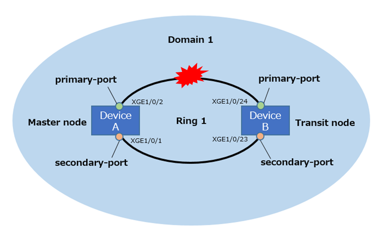
プライマリポート間の障害
プライマリポート間で障害が発生した時のステータスは下記となります。
1.デバイスA(マスターノード)
<DeviceA>display rrpp verbose domain 1
Domain ID : 1
Control VLAN : Primary 1000, Secondary 1001
Protected VLAN: Reference instance 1
Hello timer : 1 sec, Fail timer: 3 sec
Linkup-Delay timer: 0 sec
Fast detection status: Disabled
Fast-Hello timer: 20 ms, Fast-Fail timer: 60 ms
Fast-Edge-Hello timer: 10 ms, Fast-Edge-Fail timer: 30 ms
Ring ID : 1
Ring level : 0
Node mode : Master
Ring state : Failed
Enable status : Yes, Active status: Yes
Primary port : XGE1/0/2 Port status: DOWN
Secondary port: XGE1/0/1 Port status: UP
2.デバイスB(トランジットノード)
<DeviceB>display rrpp verbose domain 1
Domain ID : 1
Control VLAN : Primary 1000, Secondary 1001
Protected VLAN: Reference instance 1
Hello timer : 1 sec, Fail timer: 3 sec
Linkup-Delay timer: 0 sec
Fast detection status: Disabled
Fast-Hello timer: 20 ms, Fast-Fail timer: 60 ms
Fast-Edge-Hello timer: 10 ms, Fast-Edge-Fail timer: 30 ms
Ring ID : 1
Ring level : 0
Node mode : Transit
Ring state : LinkDown
Enable status : Yes, Active status: Yes
Primary port : XGE1/0/24 Port status: DOWN
Secondary port: XGE1/0/23 Port status: UP
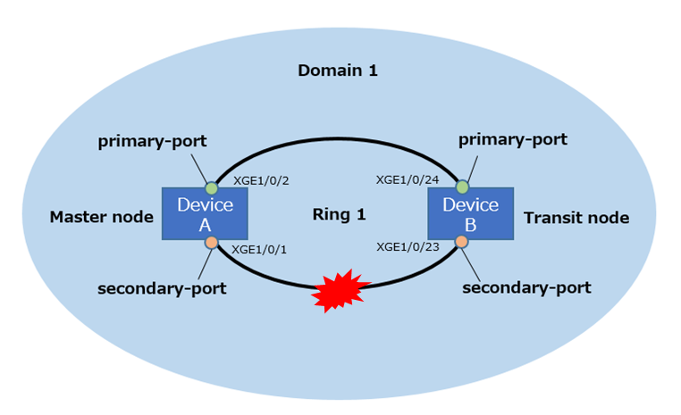
セカンダリポート間の障害
セカンダリポート間で障害が発生した時のステータスは下記となります。
1.デバイスA(マスターノード)
<DeviceA>display rrpp verbose domain 1
Domain ID : 1
Control VLAN : Primary 1000, Secondary 1001
Protected VLAN: Reference instance 1
Hello timer : 1 sec, Fail timer: 3 sec
Linkup-Delay timer: 0 sec
Fast detection status: Disabled
Fast-Hello timer: 20 ms, Fast-Fail timer: 60 ms
Fast-Edge-Hello timer: 10 ms, Fast-Edge-Fail timer: 30 ms
Ring ID : 1
Ring level : 0
Node mode : Master
Ring state : Failed
Enable status : Yes, Active status: Yes
Primary port : XGE1/0/2 Port status: UP
Secondary port: XGE1/0/1 Port status: DOWN
2.デバイスB(トランジットノード)
<DeviceB>display rrpp verbose domain 1
Domain ID : 1
Control VLAN : Primary 1000, Secondary 1001
Protected VLAN: Reference instance 1
Hello timer : 1 sec, Fail timer: 3 sec
Linkup-Delay timer: 0 sec
Fast detection status: Disabled
Fast-Hello timer: 20 ms, Fast-Fail timer: 60 ms
Fast-Edge-Hello timer: 10 ms, Fast-Edge-Fail timer: 30 ms
Ring ID : 1
Ring level : 0
Node mode : Transit
Ring state : LinkDown
Enable status : Yes, Active status: Yes
Primary port : XGE1/0/24 Port status: UP
Secondary port: XGE1/0/23 Port status: DOWN
まとめ
今回はHPE FlexFabricスイッチのRRPP設定についてご紹介しました。